Project 2: Laser Drilling Project#
Background#
You are designing an optical system to be used as part of a laser drilling system. The optical system is designed to create 11 beams from a single laser. The system consists of the following items.
Femtosecond laser
Wavelength, \(\lambda = 515 nm\)
Pulse width 290 fs
Pulse repetition rate 250 kHz
Beam diameter is 2 mm
Diffraction grating
Center 10 orders have the same optical power
Grating fabricated out of Fused Silica ZnSe (n=1.46 at \(\lambda=515 nm\))
Grating has a single depth
Minimum feature size is \(0.5 \mu m\). This means that all ridges and grooves need to be larger than \(0.5 \mu m\). But any size larger than \(0.5 \mu m\) is fine (i.e. you can have a ridge width of \(0.52145 \mu m\)).
Maximum aspect ratio of 20. This means the grating depth needs to be less than 20 * (minimum groove or ridge width).
Focusing lens
Treat as an ideal lens
Focal length, f=2 mm
Distance from last surface to focus is 6 mm
Entrance aperture is 4 mm
The system needs to create 11 beams separated by 24 \(\mu m\). Each beam needs to hit the focusing lens at different times. This is achieved by leveraging the fact that the laser is a pulsed laser. The travel time for each beam needs to be four times greater than the pulse width. The travel speed is the speed of light. This means that the length difference between any of the beams needs to be
Each beam needs to fill the focusing lens aperture. This means that the 2 mm diameter beam needs to be expanded to 4 mm.
Part 1#
Develop the optical design for the system. The design includes the following.
Period of grating
Spacing between the lenses
Focal lengths of the lenses
The lens system between the initial laser beam and the focusing lens need to be an afocal system. The afocal system needs to have an expansion of 2x. The length difference between each order needs to be greater than 0.35 mm.
Copy the following into a text file, fill in the values, and submit:
Put a zero for any element that does not exist in your design.
Grating period (m):
x1, distance between grating and lens 1 (m):
f1, focal length of lens 1 (m):
D1, diameter of lens 1 (m):
x2, distance between lens 1 and lens 2 (m):
f2, focal length of lens 2 (m):
D2, diameter of lens 2 (m):
x3, distance between lens 2 and lens 3 (m):
f3, focal length of lens 3 (m):
D3, diameter of lens 3 (m):
x4, distance between lens 3 and lens 4 (m):
f4, focal length of lens 4 (m): 0.002
D4, diameter of lens 4 (m):
x5, distance between lens 4 and the image plane (m): 0.002
Part 2#
Develop code to model the diffraction pattern of an arbitrary grating. The code should allow for an arbitrary number of transitions between glass and air segments. To keep the code compatible the first segment should be glass.
The inputs to the function should be:
x: the transition points (\(0 \lt x \lt \Lambda\)), x should include the end points \((0, \Lambda)\).
d: the thickness of the grating
lambda: the wavelength
d and lambda should be in the same units
n: the refractive index of the glass

Fig. 14 Binary grating pattern.#
The normalized grating pattern shown in Fig. 14 has the following parameters:
Refractive index, \(n=1.5\)
Total thickness, \(d=0.4 \mu m\)
Wavelength, \(\lambda=0.670 \mu m\)
Period, \(\Lambda=70 \mu m\)
Substrate index \(n_s=1.5\)
Cover index \(n_c=1.0\)
Incident angle \(\theta=0\)
x=[0, 6.0, 18.0 52.0 64.0 70.0];
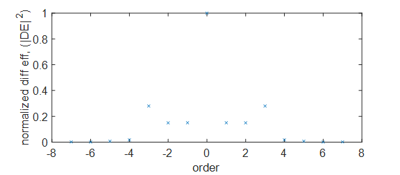
The resulting normalized diffraction efficiency for the various orders is:

Fig. 15 Normalized diffraction efficiency.#
Order |
Normalized DE |
Order |
Normalized DE |
|---|---|---|---|
Order |
DE |
Order |
DE |
-7 |
0.0017 |
7 |
0.0017 |
-6 |
0.0005 |
6 |
0.0005 |
-5 |
0.0074 |
5 |
0.0074 |
-4 |
0.0171 |
4 |
0.0171 |
-3 |
0.2799 |
3 |
0.2799 |
-2 |
0.1497 |
2 |
0.1497 |
-1 |
0.1503 |
1 |
0.1503 |
0 |
1.0000 |
Part 2 will be turned in by doing the following.
Uploading a text file with the diffraction efficiencies.
Uploading a copy of the code.
Part 3#
You need to upload a text file with your grating pattern.
Text file needs to contain the following:
x: the transition points (\(0 \lt x \lt \Lambda\)), x should include the end points $(0, \Lambda).
You need to provide a table listing the basic design parameters. Here is the list:
Parameter |
Value |
|---|---|
Wavelength (nm) |
515 |
Grating depth (nm) |
|
Grating diameter (mm) |
|
Maximum variation in 10 central beams \(\left(\frac{{DE}_{max}-{DE}_{min}}{{DE}_{average}}\right)\) |
|
Fraction of power in the central 10 beams (W) |
You need to provide a table listing all of the normalized diffraction efficiencies. Be sure to include all the possible diffraction orders including the ones diffracted into the fused silica slab.
Profile of a single grating period.
Description explaining why your design is the best design. This needs to be less than one half of a page.
